SEAM STANDARD PARTS LIBRARY
The Standard Part Type Library is a SysML library of part types where all potential fault propagations for a given part have been created according to the guidance of radiation effect experts. These part types are also organized according to part family. This library can be utilized by a user to create system models of their own circuits based on their mission environment’s radiation parameters. The following families (66 total part types) and radiation concerns are considered in the Standard Part Type Library.
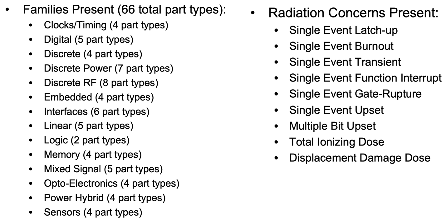
Figure X.1 Families and Radiation concernts in Standard Parts Template
Instructions for using the Standard Part Type Library
In order to incorporate the Standard Part Type Library into SEAM, the user starts with creating a new project in the Model Based System Assurance website. In Figure X. 1, we have created a new project labeled ‘test.’
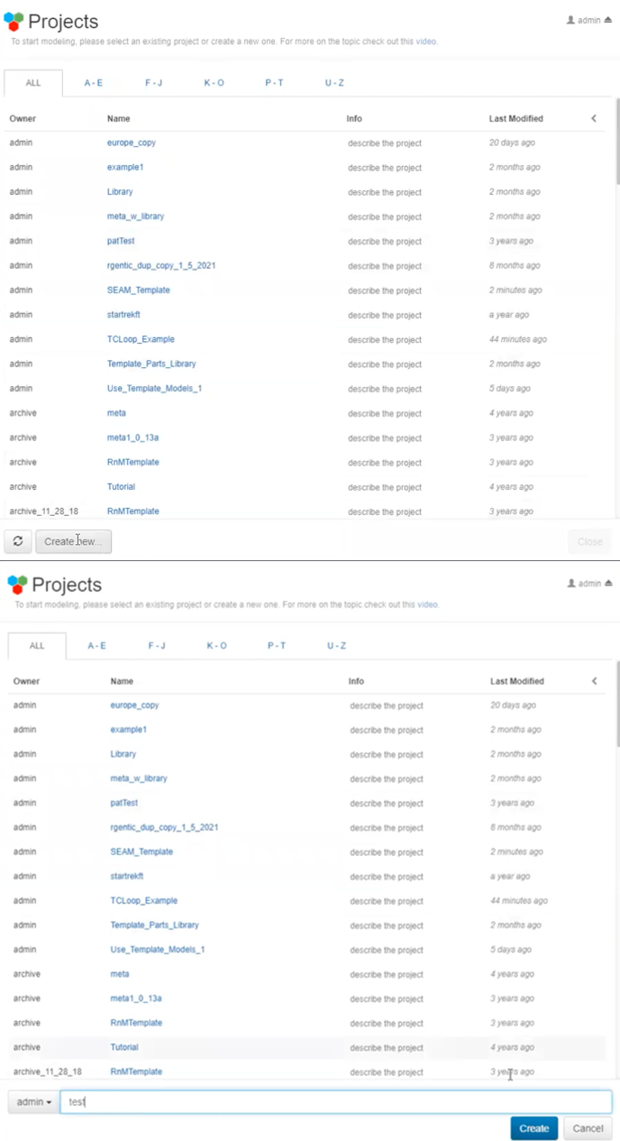
Figure X.1 New project with parts template library
After creating the project, the user adds the Standard Part Type Library directly into the new project by duplicating the project labeled ‘admin/SEAM_Template,’ shown in Figure X. 2.
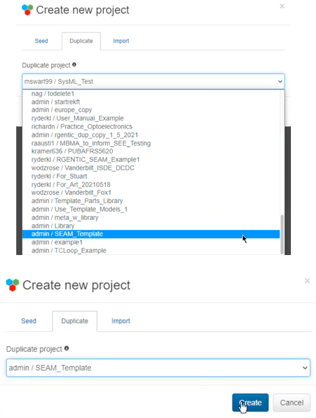
Figure X.2 New project with SEAM template
At this point, it is possible that the Standard Part Type Library needs to be updated based on when the last time ‘admin/SEAM_Template’ was updated. If this is the case, a light blue rectangle will appear on the top right of the screen. Clicking this box will ensure the Standard Part Type Library is updated based on the latest reviews by radiation effects experts (Figure X. 3).
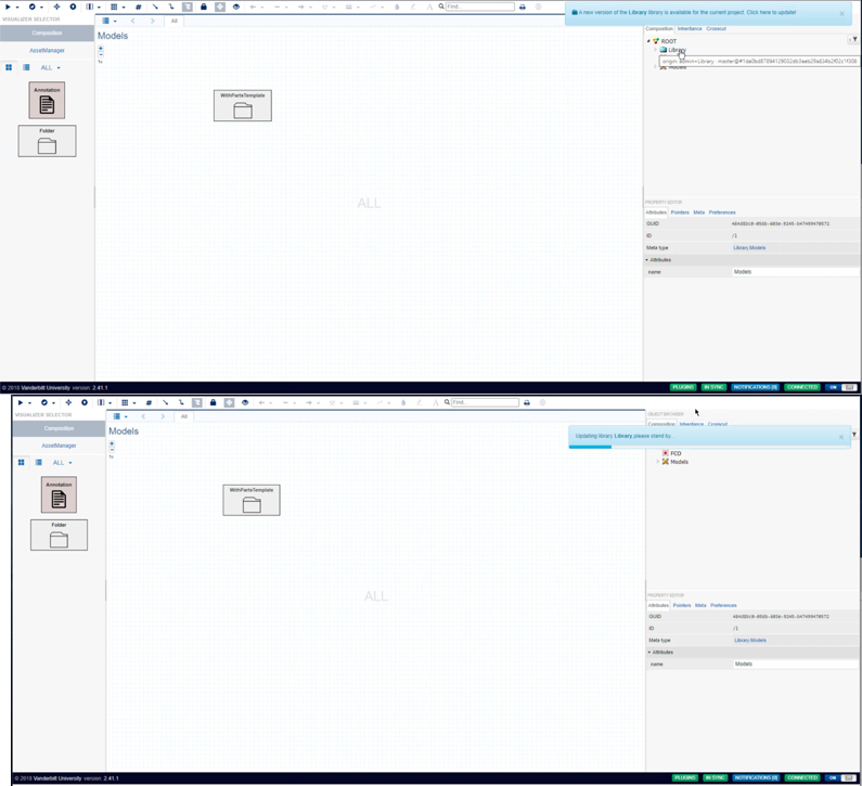
Figure X. 3. Updating the Golden Part Library (only observable if library not in the most recent version)
On the right side of the workspace, the user can click ‘Library’ to access the Standard Part Type Library. Clicking ‘Library.Definitions’ leads to models for both failure labels in ‘Library.FailureLabels’ and for part templates in ‘Library.FailureTemplate.’ This is shown in Figure X. 4.
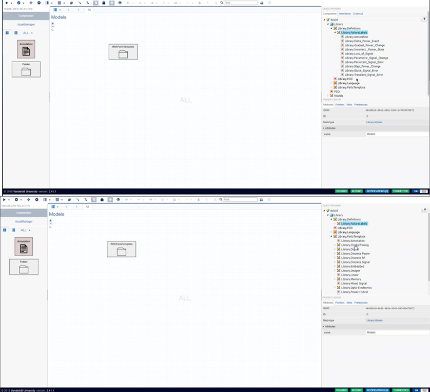
Figure X. 4. Accessing the Golden Part Type Library
Inside the ‘Library.PartTemplate,’ the user can find all part templates organized by part family (Figure X. 5).
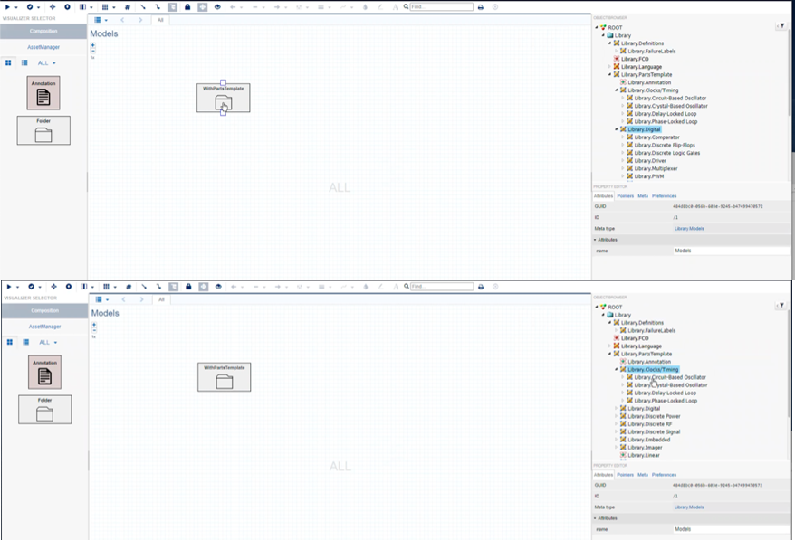
Figure X. 5. Opening 'Digital Devices' Family and ‘Clocks/Timing’ Family
Entering ‘WithPartsTemplate’ will allow the user to begin creating a Library, Function Model, and System Model for their desired circuit. Once inside this folder, the user can drag and drop a Library from the right and call it ‘Parts_Library.’ This will serve as a repository for all the user’s desired part instances from the Golden Part Type Family. At this point, the user can also drag and drop the ‘System_Model’ folder, which will serve as the place for all schematic construction using the part instances in the ‘Parts_Library’ folder. Both are shown in Figure X. 6.
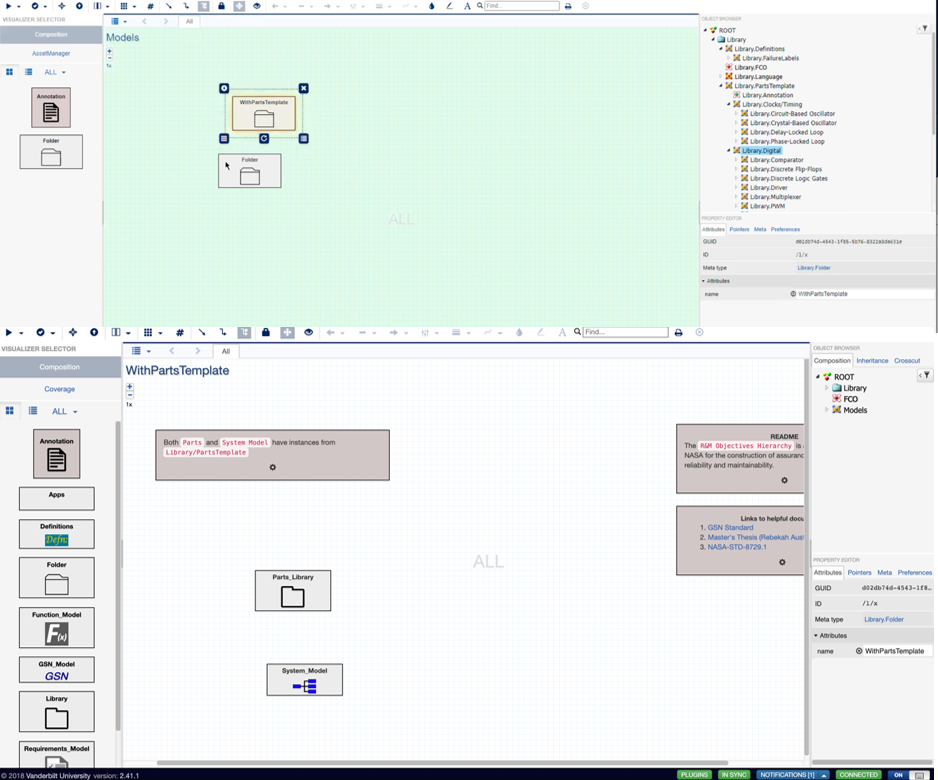
Figure X. 6. Creating an appropriate area to contain the user’s preference of part templates
Once inside the ‘Parts_Library’ folder, the user can drag instances of part templates into this location. By holding the ‘control’ button, the user can drag and drop an instance from the Golden Part Library onto the workspace. In this example’s case, we dragged and dropped an FPGA block and a Microcontroller block. If a pop-up box appears and asks whether to ‘Create instance here’ or ‘Copy here,’ choose ‘Create instance here.’ Overall, creating instances of part types allows the user to modify the part type template within their project. Specifically, it will maintain a link to the user’s library model found in the ‘Parts_Library’ folder. Another benefit is that updates to the Standard Part Type Library by radiation experts will continue to be carried over into the user’s specific part library in the ‘Parts_Library’ folder. One final note is that inside an instance’s part template (which can be accessed by double clicking the instance part template), we can adjust radiation effects but not delete them. These steps can be visually seen in Figure X. 7.
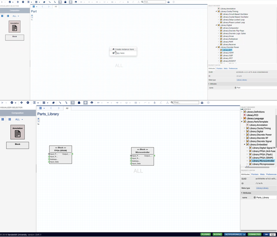
Figure X. 7. Creating instances from Golden Part Library
Now that we have created a parts library within the ‘Parts_Library’ folder with relevant instances, the user can create a system model. The user can exit the ‘Parts_Library’ folder by clicking the ‘upward-directed arrow’ symbol on the upper left of the screen. The user can then split the screen into two vertical screens by clicking the top left icon that looks like a book. This feature is useful for looking at a system model while also looking at our instance part library, all actions can be observed in Figure X. 8.
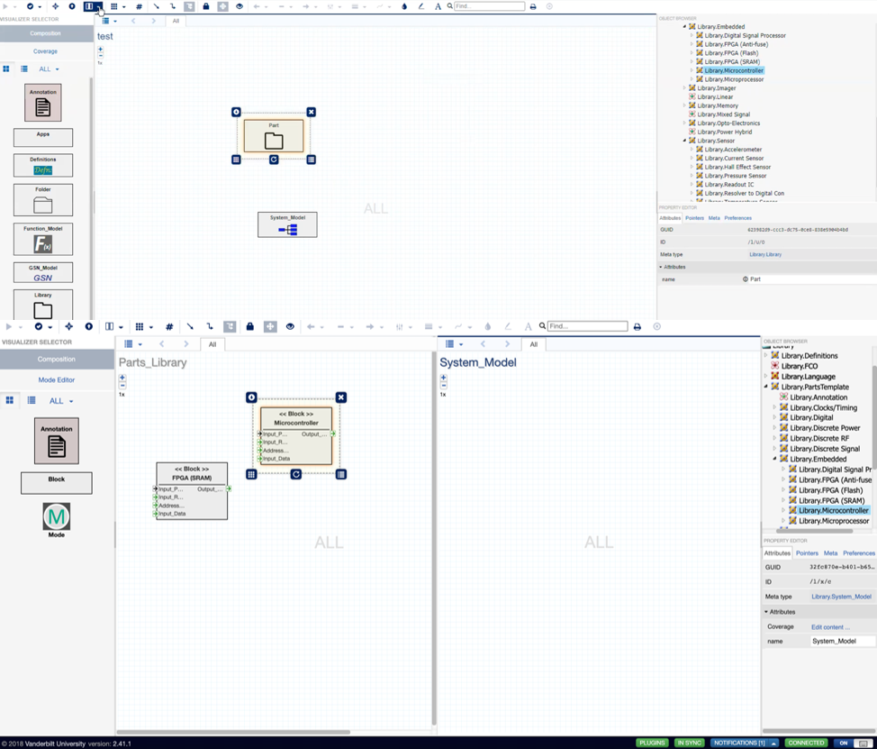
Figure X. 8. Splitting the screen into two vertical screens
With both the part library and the system model folder open, the user can begin creating a system failure propagation model for their circuit. To accomplish this, the user will need to hold the alt key and drag a part instance from the part folder on the left into their system model on the right. Multiple instances of the same part can be created in this manner, and the names of each instance can be changed by going into the attributes of a specific instance. This attributes section can be found on the bottom right of the screen when clicking an instance (after it is in the ‘System_Model’ folder). The user can then alter the name (Figure X. 9).
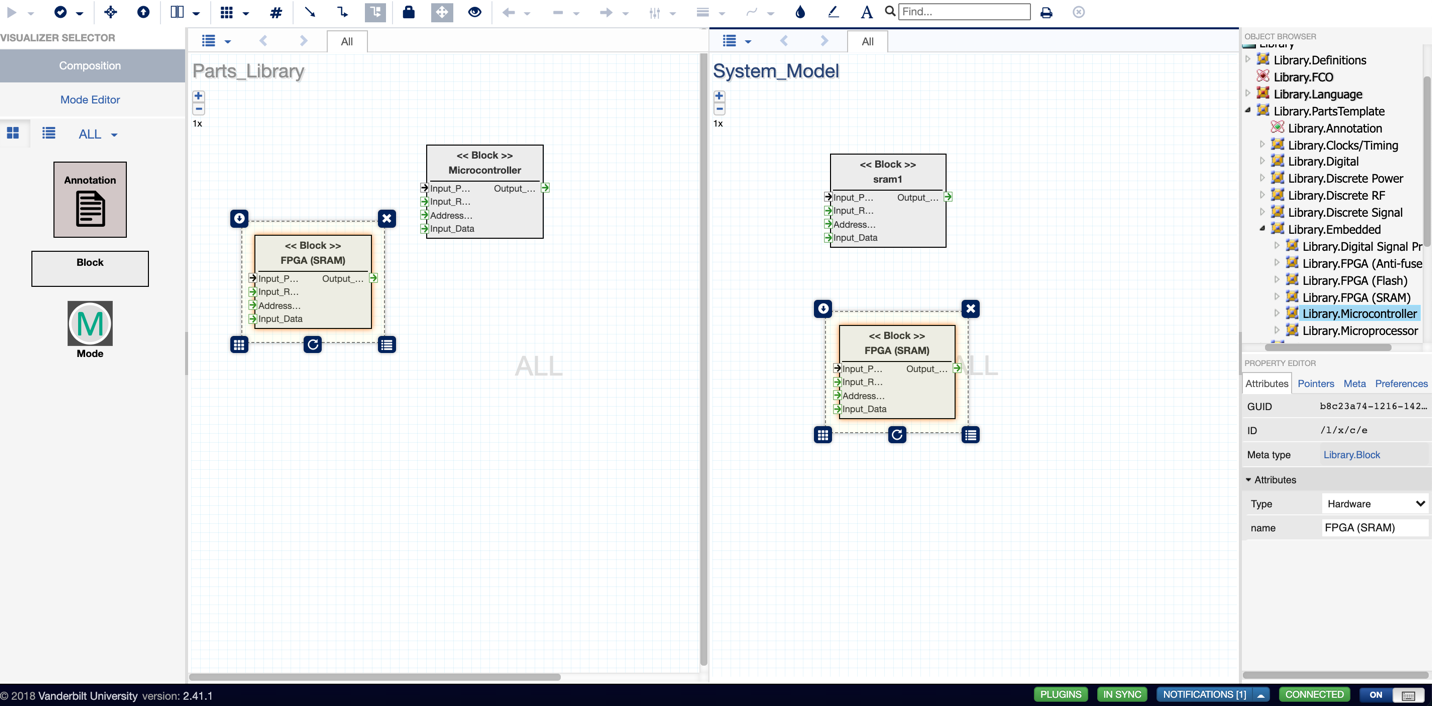
Figure X. 9. Creating instances in the 'System_Model' folder and changing the name of each instance in the attributes section
Blocks can then be connected to each other in a way analogous to wiring electronic components together. However, the user must first decide upon which ports to connect to each other. It should be done according to the circuit’s system architecture. Connections cannot be made between blocks in the ‘Parts_Library.’ The ‘Parts_Library’ will not allow those connections to occur (Figure X. 10).
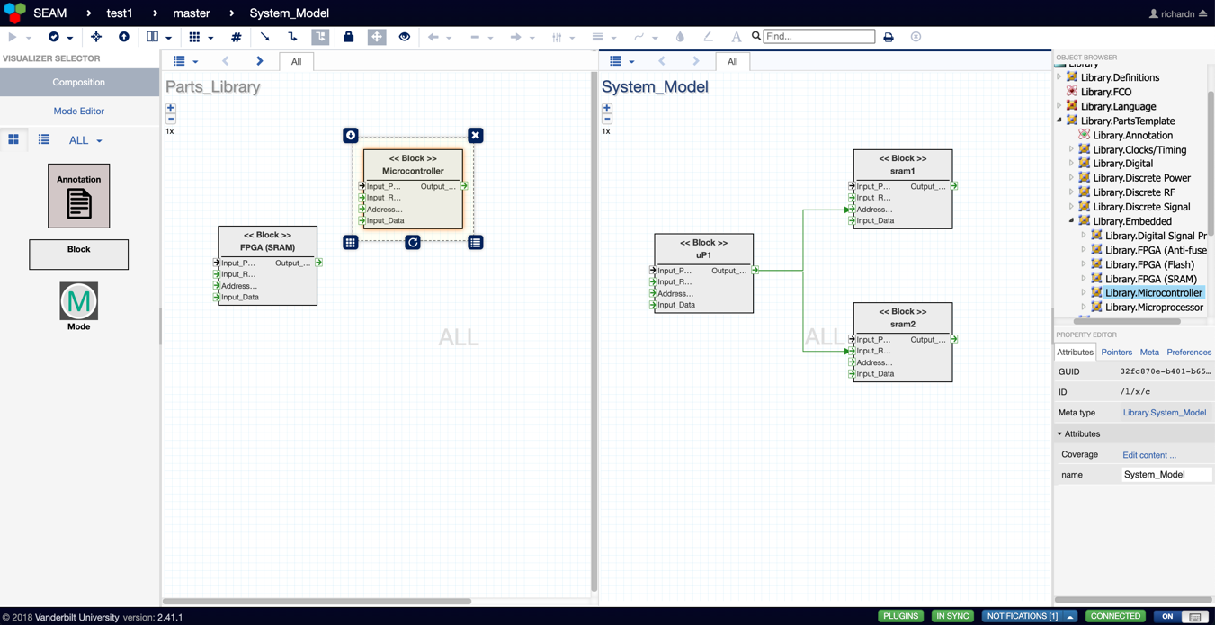
Figure X. 10. Wiring the part instances to each other via the ports
As mentioned previously, the SysML faults can also be accessed within each part instance by double clicking the block (Figure X. 11). This provides the user a means of understanding how the faults propagate through that specific part instance (from a given input to its output).
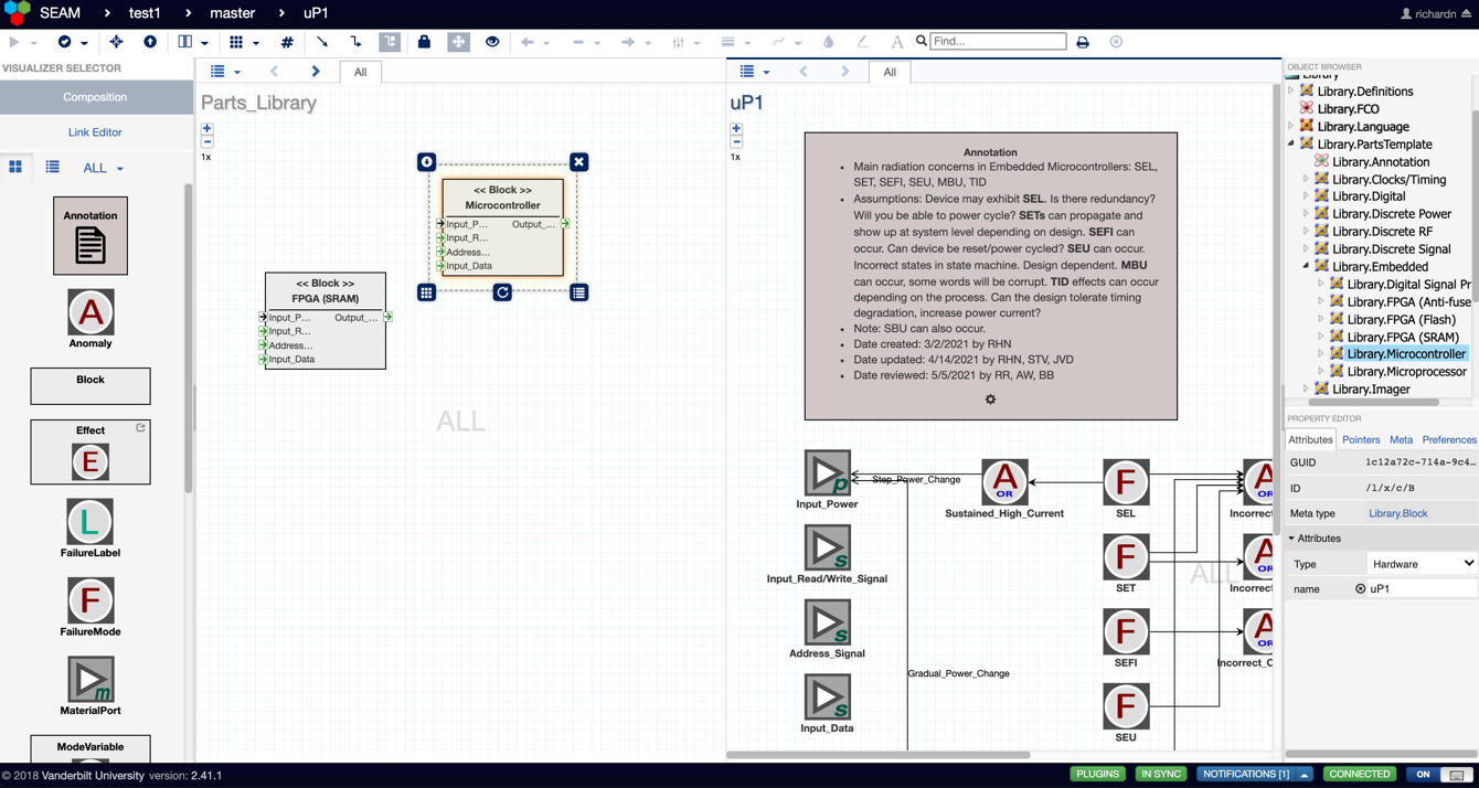
Figure X. 11. Observing how fault propagation occurs through a part instance's input to its output
The line placement of error labels can be adjusted by clicking the icon that shows three lines with filled-in boxes on them (on the top row). Clicking this icon allows the user to readjust the error labels into three different positions: left-side, center, or right-side (Figure X. 12)
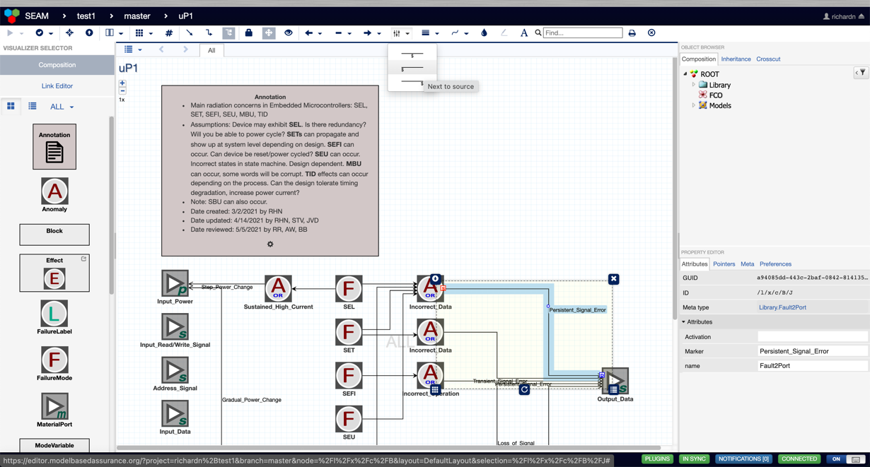
Figure X. 12. Adjusting source label placement
The routing of lines can be altered in three distinct ways. Clicking the 'straight arrow’ icon results in all lines becoming straight lines. Clicking the ‘straight arrow with 90˚ edges’ icon results in all arrows bending at 90˚ edges to best reach its destination. Clicking the ‘straight arrow with 90˚ edges and filled box in upper right’ icon allows the user to determine the location of those 90˚ edges. Specifically, the user will need to double click at a particular part of the line and drag that point to the user-degsired location (Figure X. 13)
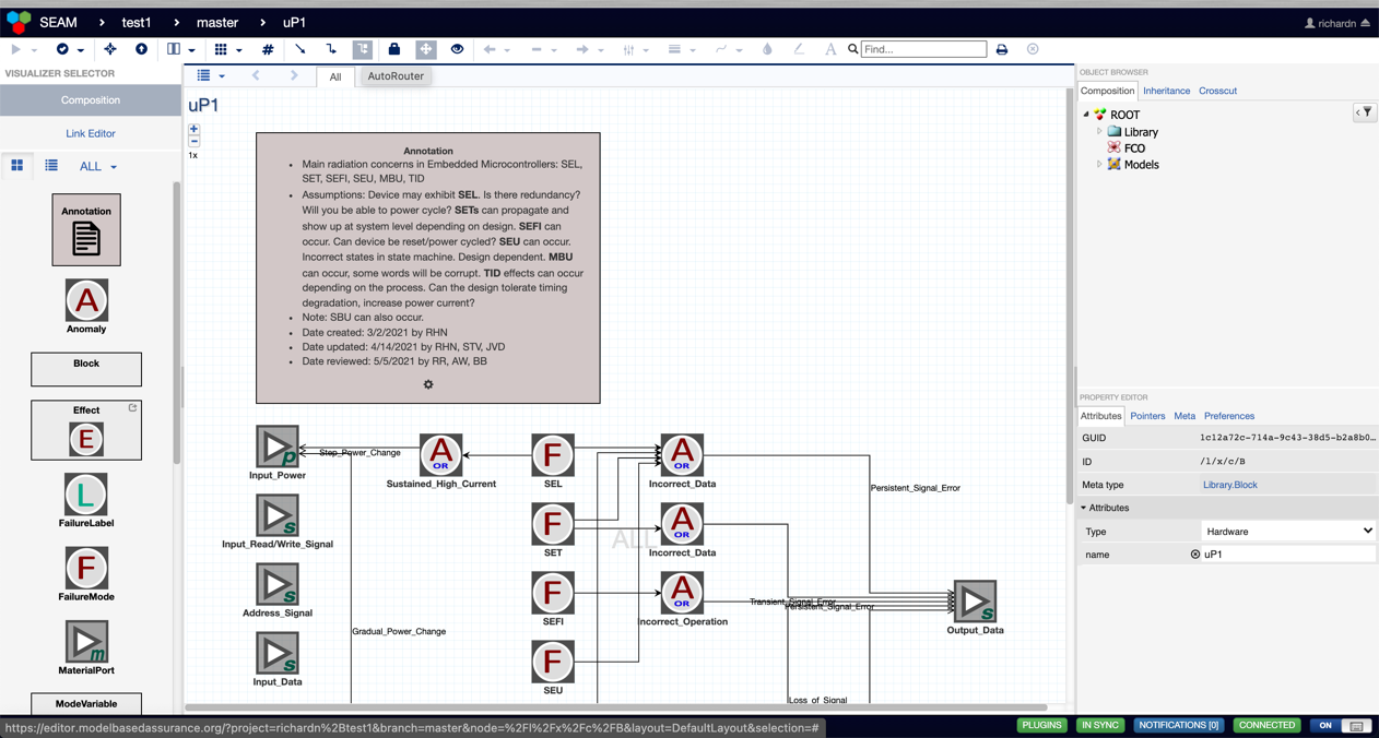
Figure X. 13. Adjusting router of line
To create a function model, the user can leave the split screen mode, and drag and drop a ‘Failure_Model’ library from the left-hand side onto the screen (Figure X. 14).
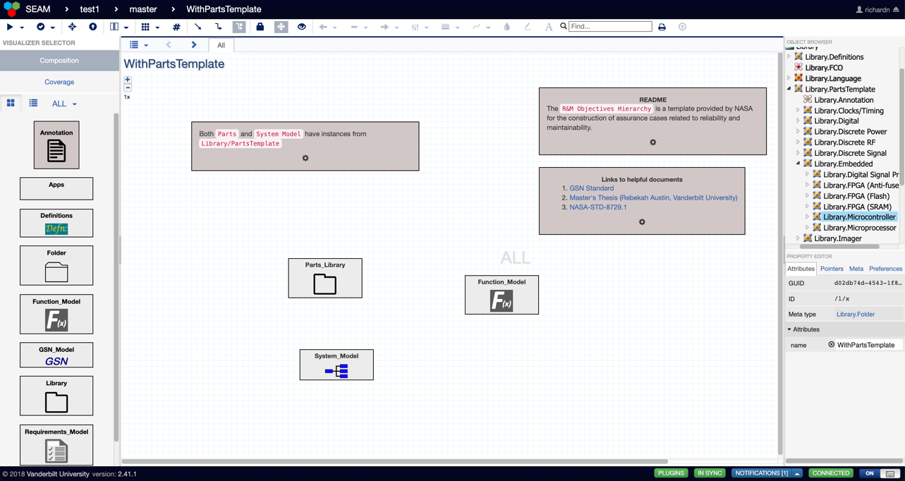
Figure X. 14. Creating a Function Model based on the Golden Part Family Template
The user can double click inside the ‘Failure_Model’ folder and drag and drop Top Functions and Primitive Functions onto the screen (Figure X. 15). These functions show how functions can potentially fail due to radiation effects. These failure modes can be connected to each other via the ports.
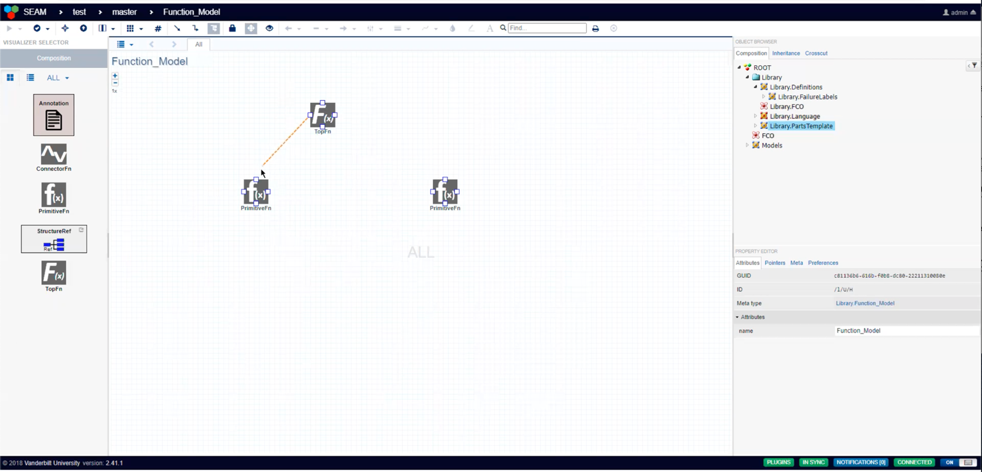
Figure X.15. Creating and connecting functions
If the user desires to reference a system model in the function model, the user can return to the split screen mode and have the system model folder open on the right side of the screen. Then, the user can hold the shift key and drag blocks from the system model onto the function model screen (Figure X. 16).
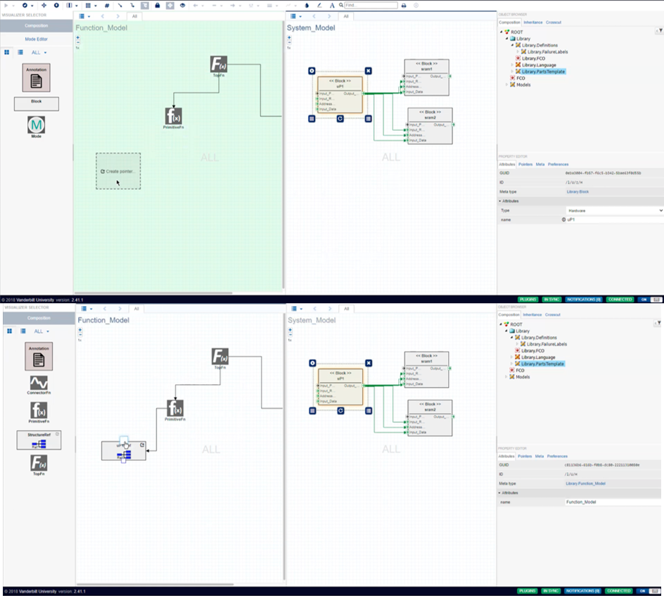
Figure X. 16. Creating system model references in the function model