Functional Decomposition Models
The Functional Decomposition Model (FDM) of a system demonstrates what functions the system implements and how they relate to components of the system. The functions themselves are descriptions of capabilities set by requirements/specifications, and represent a form of abstraction for assessing reliability, availability, and safety of a system. The system takes the form of a hierarchical assignment of responsibility for the accomplishment of a function to sub-functions and components.1
Definition of Boxes
Functions, represented as F(x), are connected to sub-functions, represented as f(x)), which are connected to specific instances of components that support the sub-function1. In the figure below, only one component is associated with each sub-function. However, in practice, each sub-function can be associated with as many component instances as necessary1.
In a typical system, the sub-functions (most often) involve one of the following: power, sensing, computation, actuation, or radiation effect mitigation. Functions typically refer to one of the following: a form of user input or output, or a form of remote communication1.
Creating a Functional Decomposition Model
In order to create a Functional Decomposition Model, the user must first drag and drop a ‘Function_Model’ folder from the left side of the screen in Figure VII. 1 onto the main workspace. It is important to note that Figure VII. 1 has been prefilled and would normally appear empty for a new project.
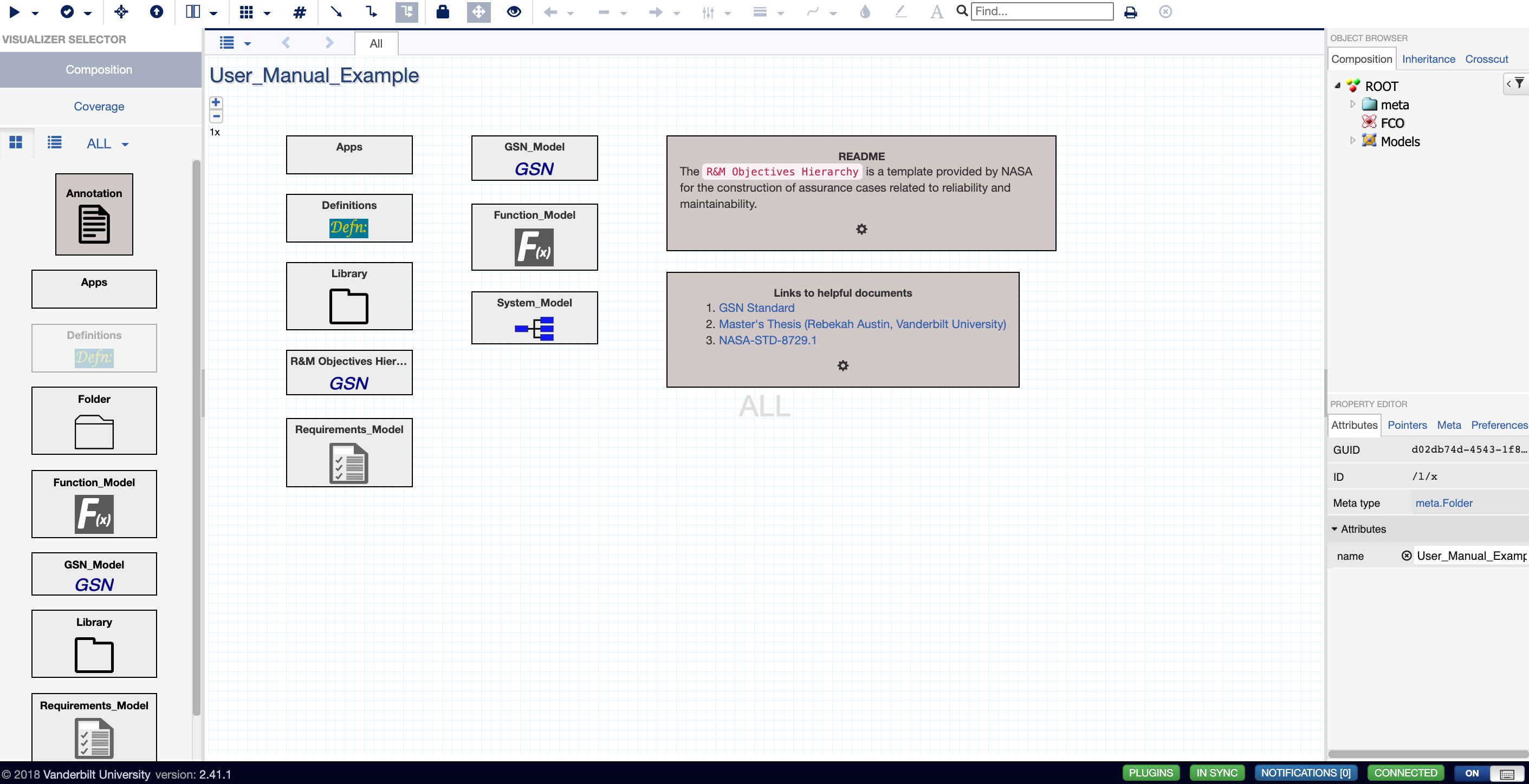
Figure VII.1. Workspace where user drags and drop a ‘Function_Model’ Library onto the workspace
After double-clicking into the ‘Function_Model’ folder, the user can construct the Functional Decomposition Model (Figure VII. 2). The user can drag a top function block from the left side of the screen onto the workspace. The user can also relabel that function by clicking the block, looking to the attributes section on the bottom right side of the screen, and changing the name for that block.
The user can create primitive functions in the same manner, as well as rename the primitive functions in the same manner. Once all user-desired top functions and primitive functions are added onto the workspace, the user can connect top functions to primitive functions by hovering over the top function, clicking one of the sides of the block, and dragging it to one of the inputs of the primitive functions. The ‘Power-Ref,’ ‘Sensor-Ref,’ ‘Microcontroller-Ref,’ and ‘Output-Ref’ are examples of linking SysML models into the Functional Decomposition Model and will be discussed in Chapter 8 (titled “Linking Models”).
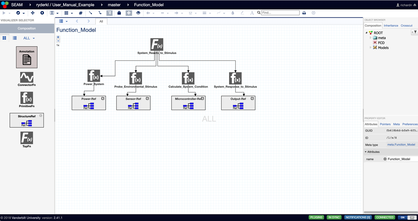
Figure VII.2. Completed Functional Decomposition Model
Example Functional Decomposition Models
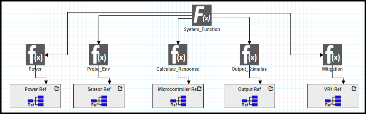
Figure VII.3. Example of a Functional Decomposition Model [1]
Figure VII. 3 represents an example of a functional decomposition model. It begins with a high-level function F(x) and branches off into multiple smaller sub-function (or primitive functions) f(x). These sub-functions vary for Power functions, Sensing function (for probing the environment and system itself), Calculate Response function, Output Stimulus function, and Mitigation function. Through linkage, these subfunctions can be connected to SysML models (which will be discussed in Chapter 8 titled “Linking Models”).
Functional Decomposition Model Resources
- K. L. Ryder et al., “SYSTEMS ENGINEERING AND ASSURANCE MODELING (SEAM): A WEB-BASED SOLUTION FOR INTEGRATED MISSION ASSURANCE,” Facta Universitatis, Series: Electronics and Energetics, vol. 34, no. 1, Art. no. 1, Feb. 2021.