Goal Structuring Notation (GSN) Models
Goal Structuring Notation (GSN) assurance cases are used to document and develop assurance cases and can be developed in parallel with the SysML and Functional Decomposition models within the SEAM tool. Assurance cases are “reasoned, and compelling arguments supported by evidence that a system will operate as intended for a given, defined environment ”. Assurance cases document an argument, but do not ensure the truth of the argument; assurance cases based on faulty reasoning or premises can lead to premature system failure. References to the GSN Community Standard and NASA Std 8719.1A are provided within SEAM, and the NASA R&M Objectives Hierarchy (from NASA Std 8719.1A) is provided in GSN format for reference. This chapter describes how to make GSN assurances cases in SEAM and provides a GSN example and GSN-based resources. Linking a GSN assurance case with other SEAM models such as fault propagation model is described in Chapter VIII – Linking Models.
Definition of GSN Elements
GSN is a method of graphically documenting an assurance case that provides a standard for structuring the argument. The various GSN model elements and their definitions are presented below. GSN models typically start with a goal for the system. This goal may be conditioned by a context, such as mission environment and duration, which frames how goals and strategies should be interrupted. A strategy is developed for meeting the goal. From there, sub-goals and sub strategies are used to break the argument down until a goal or strategy can be supported by a solution. Solutions are evidence for the argument, and can be test reports, simulation results, or any other piece of information that supports the claim being made. Justifications are used to explain why goals and strategies are acceptable in the argument. Other elements are available in the SEAM GSN models that allow for the assurance case to be connected to other SEAM models.
| NAME | IMAGE | DESCRIPTION |
|---|---|---|
| Assumption |  | Assumption boxes are used to document what assumptions are being made about a strategy, goal, or solution. |
| Choice Junction |  | Choice junctions allow for M out of N logic paths to be used to prove a goal. |
| Context |  | Context boxes are used to frame how a claim or set of reasoning should be interpreted. |
| Goal |  | Goal Goals are the claims the assurance case are trying to prove. |
| GSN Model | Contains a GSN model that can be linked to or used as a sub-model. | |
| InContextRef |  | Reference to contexts used elsewhere in a SEAM GSN project. |
| Justification |  | Justifications provide an explanation as to why a certain claim or argument is acceptable. |
| Requirement Reference |  | Reference to project requirements that are contained in the project’s Requirements Model. |
| Solution |  | Solutions provide evidence supporting the truth of an argument. |
| Strategy |  | Strategy Strategies are reasoning steps to help show the validity of the goal. |
| Support Reference |  | Support Reference Reference to support material used elsewhere in the SEAM project. |
NASA R&M Objective Hierarchy
The NASA Reliability and Maintainability (R&M) Standard “specifies technical objectives and related strategies for NASA programs and projects to be used in planning, executing, and evaluating Reliability and Maintainability.” A version of the R&M Hierarchy is included in GSN format for reference, and was briefly discussed in Chapter 4. Figure V.1 shows the top-level view of the R&M Hierarchy which specifics the overall top-level goal for a system, “performs as required over the lifecycle to satisfy mission objectives,” a top-level strategy, and four subgoals that work to meet the overall top-level goal. These subgoals provide excellent starting places for GSN arguments for many different types of systems.
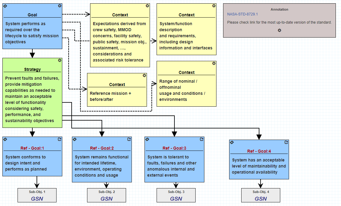
Figure V.1 NASA R&M Objective Hierarchy in SEAM GSN format as a reference for users.
Creating a GSN Model
Starting a GSN model from scratch begins with the canvas shown in Figure V.2. The simulation space (given by the orange box) is initially empty. GSN elements can be dragged and dropped from the list on the left (red box). The Object Browser (green box on the right) provides a means of navigating to other models within the project and the Property Editor (blue box on the right) is used to modify properties of the GSN elements.
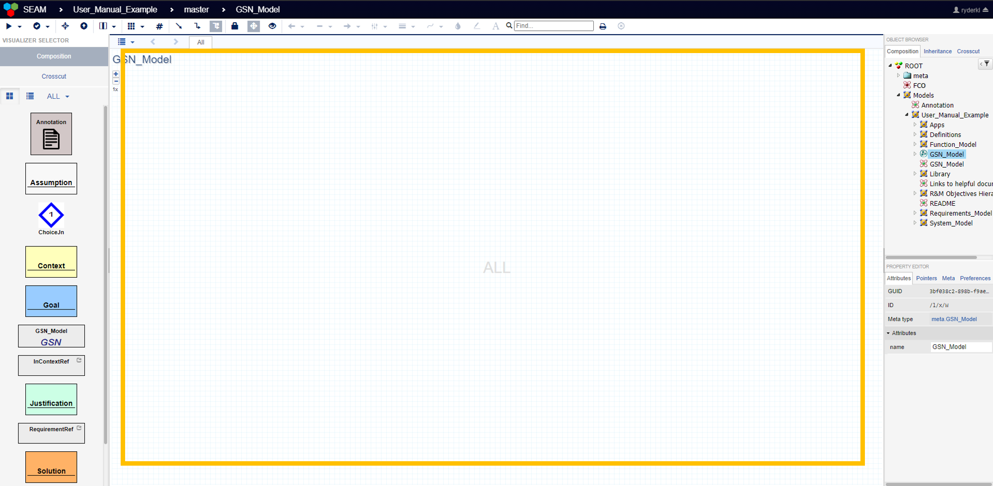
Figure V.2. Empty GSN model. GSN elements (red box) can be dragged and dropped into the simulation space (yellow box) to create GSN models. The property editor (blue box) is used to manage the properties of the GSN elements and the object browser (green box) can be used to navigate to different models within the project.
Once a GSN element has been placed in the simulation space its properties can be changed, and text can be added. Figure V.3 shows a goal element that has been placed into the simulation space (upper left), as well as the element’s Property Editor (upper right), and the element’s Edit Description box (bottom). Clicking on the cog icon (orange box) brings up the Edit Description box, which allows users to add text descriptions to the GSN elements. This is where the actual goals, solutions, etc. would be typed out by the user. Right clicking on the GSN element once brings up its properties in the Property Editor. For GSN elements, the most important properties are the “In Development” true/false flag, the “Meets Criteria” dropdown box, and the “name” text box. The “name” property is used to give unique names to the GSN elements. Here, the element’s name is “Goal,” however it could be changed to something more specific, like “Goal 1.A.” The “Meets Criteria” dropdown box allows for GSN elements to be tagged as meeting criteria, not meeting criteria, partially meeting criteria, or it is unknown if it meets criteria. This creates a record of which arguments satisfy the claim being made and which do not. Finally, the “In Development” flag marks which GSN elements are completed, and which are still being developed. The diamond mark on the GSN element in Figure V.3 (red box) denotes that this element is still in development. When the flag is set to false, the diamond will disappear, allowing users to easily see which elements are still in development and which are complete.
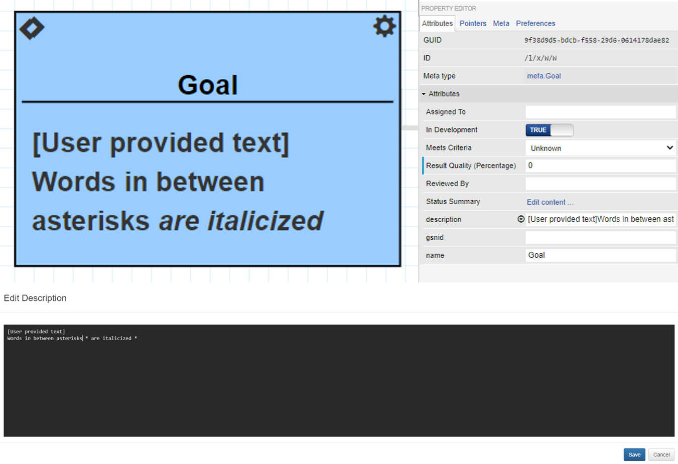
Figure V.3. A Goal GSN element (top left). The Goal’s text can be edited by clicking on the cog (orange box), which brings up the Edit Description prompt (bottom). The property editor (top right) shows the different attributes of the element that can be modified. This GSN element is still in development (red box)
All GSN elements contain the same set of properties and test boxes. By adding different GSN elements and linking them together, a GSN argument can be constructed. Table V.2 provides a list of the possible connections for the basic GSN elements from Table V.1. The solid lines represent connections in the argument, while dashed lines represent supporting documentation for the specific element the arrows are coming from.
**Table V.2 GSN Elements Connections.**| CONNECTION | IMAGE | DESCRIPTION |
|---|---|---|
| Goal-to-Strategy Strategy-to-Goal |  | Goals and Strategies can be connected to each other in either direction. |
| Goal-to-Solution Strategy-to-Solution |  | Goals and Strategies both connect to Solutions. Solutions are unable to form connections. |
| Goal-to-Assumption Strategy-to-Assumption |  | Goals and Strategies both connect to Assumptions. Assumptions are unable to form connections. |
| Goal-to-Context Strategy-to-Context |  | Goals and Strategies both connect to Contexts. Contexts are unable to form connections. |
| Goal-to-Justification Strategy-to-Justification |  | Goals and Strategies both connect to Justifications. Justifications are unable to form connections. |
A complete GSN argument would have no elements marked as still in development, and preferably all argument chains would be labeled a meeting criterion.
Example GSN Model
An example GSN model has been made for a generic embedded system. The generic embedded system example is used throughout Chapters V – VIII to demonstrate the various capabilities within SEAM. GSN models for more specific systems can be found in the references provided at the end of the chapter. Figure V.4 shows the top-level goal for this system: “System is able to register environmental stimulus for intended lifetime, environment, operating conditions, and usage,” which just means that the example system remains operational for the duration of the mission. This goal was taken directly from the NASA R&M Hierarchy (described in the next subsection), but in a realistic system the top-level goal would be more specific to the mission objectives. Context for the top-level goal, provided next to it, includes the proposed mission environment such as the orbit and mission lifetime. Other types of context may include functional and behavioral models of the system and mission constraints such as size, weight, and power constraints. The top-level strategy for this GSN model is to “prevent faults and failures, provide mitigation capabilities as needed to maintain an acceptable level of functionality considering safety, performance, and sustainability objectives.” This strategy was taken directly from the NASA R&M Hierarchy as a starting point for developing this model.
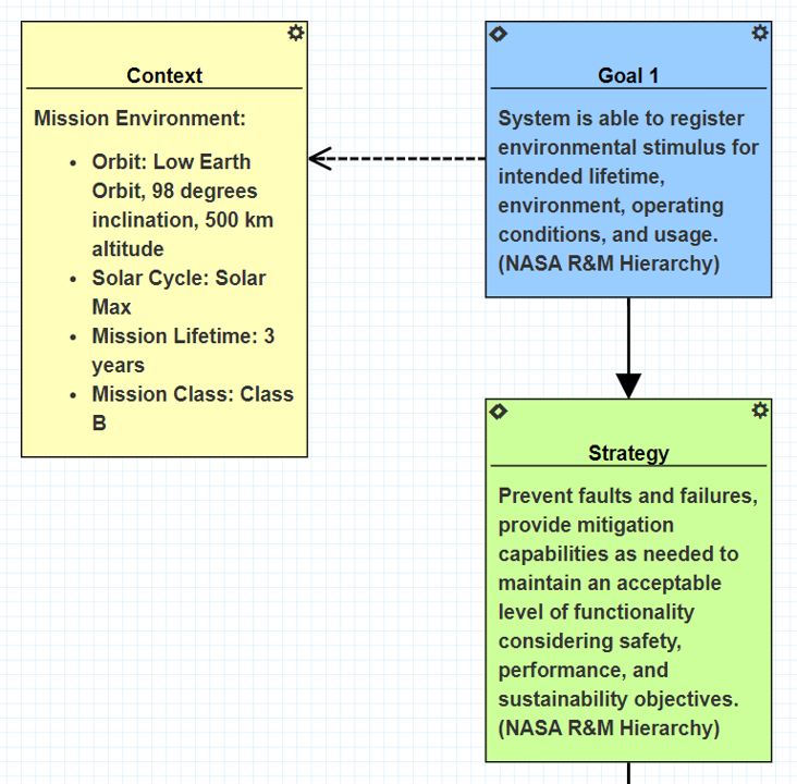
Figure V.4. Top-level goal, top-level strategy, and mission environment context for an example GSN argument.
Beneath the top-level goal and strategy, sub-goals and sub-strategies are used to breakdown the argument until a goal can be supported directly by a piece of evidence. Figure V.5 shows some of the sub-level goals that help support the top-level goal and strategy. To ensure this example system can meet its top-level goal, the system needs to be “tolerant to faults, failures, and other anomalous internal and external events,” as do each of the system’s subsystems.
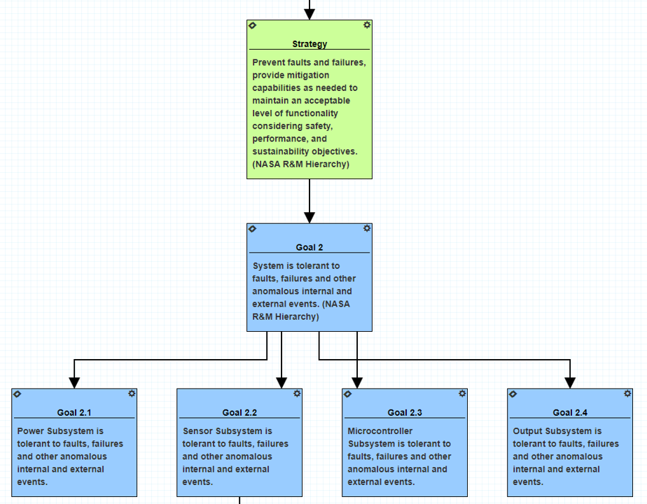
Figure V.5. Sub-goals used to support the top-level strategy.
Sub-goals continue to be broken down into more sub-goals and sub-strategies until a goal can be supported directly with evidence and then marked complete. Figure V.6 shows the rest of the GSN argument for Goal 2.2 “Sensor Subsystem is tolerant to faults, failures, and other anomalous internal and external events.” This sub-goal has one strategy that was taken from the NASA R&M Hierarchy, and two sub-goals have been identified as paths toward demonstrating the Goal 2.2 has been met. These sub-goals are specifically related to the possible radiation effects, total ionizing dose (TID) and single event effects (SEEs), that may occur in the Sensor Subsystem. Both sub goals 2.2.1 and 2.2.2 are considered complete because they have completed solutions that show the goals have been met. Testing was done for both types of radiation effects and the Sensor Subsystem was found to remain within specifications. Test reports could be attached to these solutions as evidence of the goals being met. Goal 2.2.2, which relates to SEEs, also has a justification attached to it., which explains why some amount of SEEs in the Sensor Subsystem are considered acceptable to the overall project.
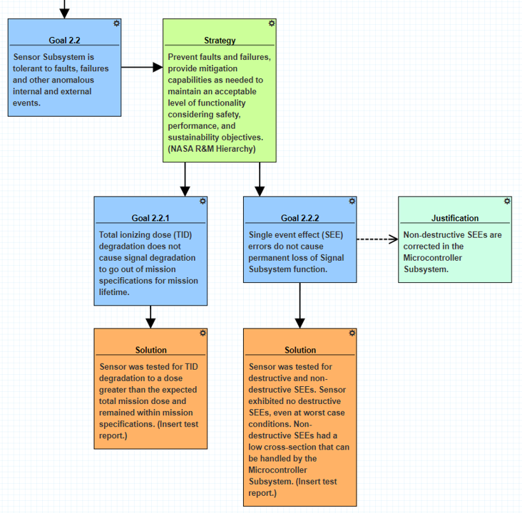
Figure V.6. A completed GSN argument for sub-goal 2.2 with solutions that can be supported by evidence and justifications for why certain behaviors are acceptable.
Goal 2.2 is considered complete and the “In Development” marker does not appear on any of the arguments beneath it. In order for the top-level goal to be complete, all sub-goals beneath it need to have completed arguments and no longer be “In Development.” Once that is true, the GSN argument is considered complete. It should be reiterated that a complete GSN argument does not necessarily mean the argument is true and valid, or that the argument will not change during a project’s lifetime.