SYSTEMS MODELING LANGUAGE (SYSML) MODELS
Systems Modeling Language (SysML) is a graphical language for systems engineers, for representing a complex system in terms of its structure, behavior, and dependencies. The model construction process utilizes and arranges SysML “blocks” in such a way that it captures the system’s architecture and its behavior . Specifically, the blocks represent all possible means by which the system can respond to environmental stimulus. This type of schematic, which consists of blocks in their correct arrangement according to its system architecture, can be presented to non-technical contributors (e.g., customers, funders, etc.) because it is an intuitive top-level view of the system. Also, as can be inferred, SysML is also useful in managing the development of complex systems and enhancing knowledge capture.
Definition of Boxes
A SysML block diagram describes the system’s structure by focusing on the flow of information (data) and power through the system. The diagram is composed of blocks and interconnections. A block (Figure VI. 1, top image) represents a system component that encapsulates all the details of that component (for example, constraints and properties). The name of the block can be changed by going to the ‘Attributes’ section on the right side of the work screen and changing the block’s name in ‘name’ (Figure VI. 1, top image). It is also possible to change the border color of the SysML block by going to ‘Preference’ on the right side of the screen (after clicking the block) and clicking the empty rectangle next to ‘borderColor’ under ‘Color.’ Similarly, the color of the SysML block itself can be changed by clicking the empty rectangle next to ‘color’ (Figure VI. 1, middle image).
Ports on the blocks represent interfaces that can allow blocks to connect with each other via interconnections. These interconnections represent how the blocks interact with each other.2 The colors of a connection between blocks can be adjusted by clicking the connection and going to ‘Preference.’ From there, the user can change the color by clicking the empty rectangle next to ‘color’ under the ‘Color’ tab (Figure VI. 1, bottom image).
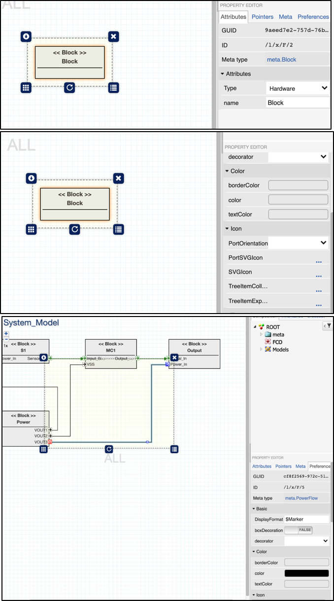
Figure VI.1. All properties of a SysML Block
Creating a SysML Model
To create a SysML model, the user must first create a ‘System_Model’ library folder and enter it (Figure VI. 2).
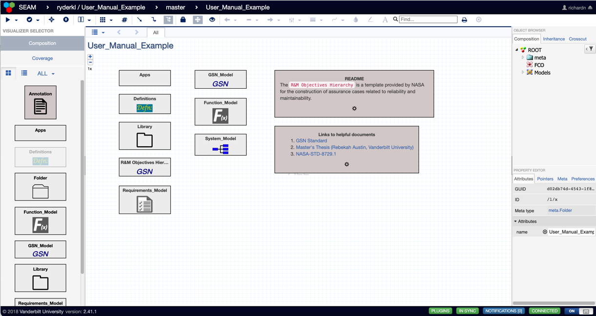
Figure VI.2. Workspace containing the ‘System_Model’ Folder.
This folder already has a pre-created SysML schematic (Figure VI. 3). It consists of four blocks interconnected in various ways. In order to create a block (Figure VI. 4), the user will need to drag and drop a block from the left-side bar onto the screen. Blocks can be connected via ports.

Figure VI.3. System Architecture Schematic within the ‘System_Model’ Library Folder
Figure VI.4. Example of a SysML block. In this case, it is a Sensor block.
Double-clicking inside any of these blocks (such as Figure VI. 4) allows the user to view the failure modes within the clicked block (Figure VI. 5). In the case of the Sensor block, we see an input power port (‘Power_In’) two ‘Failure Modes’ (Total_Ionizing Dose and Single_Event_Effect), two ‘Anomalies’ (Degraded_Signal and Transient_Incorrect_Signal), and one output signal port (Sensor_Output). The two anomalies also have failure labels identifying how the anomalies are expressed at the output port. For example, ‘Persistent_Signal_Error’ is an error that can be recovered from by resetting the system. ‘Stuck_Signal_Error’ is an error that causes permanent damage and cannot be changed back. All other failure labels can be found in Figure VI. 6, with definitions for each failure label located on the right box titled ‘Annotation’ in Figure VI. 6.
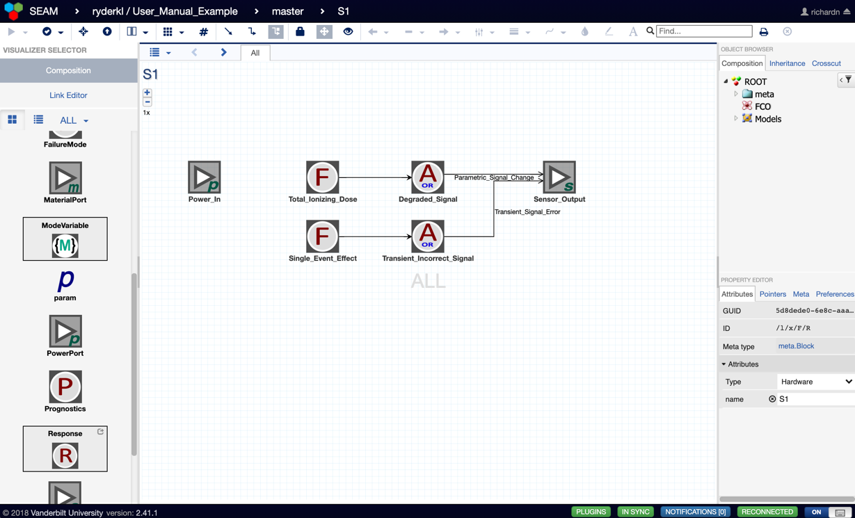
Figure VI.5. Schematic of Failure Modes for the Sensor Block
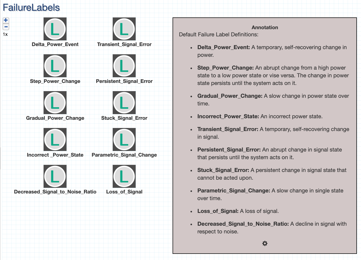
Figure VI.6. . List of all possible Failure Labels with definitions
Example SysML Model
A SysML block diagram can be found in Figure VI. 7. This figure represents a sensor by showing all the individual subsystems that compose this system: the sensor subsystem, the microcontroller subsystem, the output subsystem, and the power subsystem.
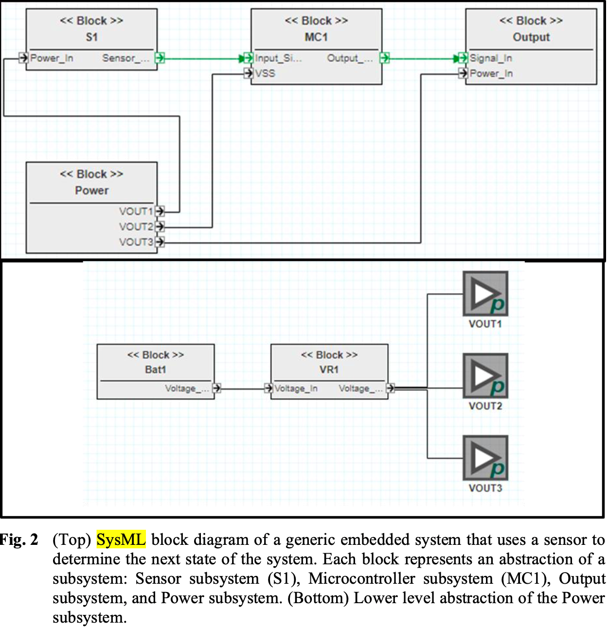
Figure VI.7. SysML block diagram of a system using a sensor. Each block represents an abstraction of a subsystem: Sensor subsystem (S1), Microcontroller subsystem (MC1), Output subsystem, and Power subsystem3
SysML Model Resources
- Object Management Group, “SysML Diagram Tutorial,” SysML.org. https://sysml.org/res//tutorials/sysml-diagram-tutorial/index.html (accessed Sep. 08, 2021).
- K. L. Ryder et al., “SYSTEMS ENGINEERING AND ASSURANCE MODELING (SEAM): A WEB-BASED SOLUTION FOR INTEGRATED MISSION ASSURANCE,” Facta Universitatis, Series: Electronics and Energetics, vol. 34, no. 1, Art. no. 1, Feb. 2021.